Air Hose Reel,Mini Air Hose Reel,Air Compressor Hose Reel,Industrial Air Hose Reel NINGBO QIKAI ENVIRONMENTAL TECHNOLOGY CO.,LTD , https://www.hosereelqikai.com
1 Reasons for poor heat transfer In the heating system, the main function of the heat exchanger is to prepare hot water for the user. The heat source comes from the heating network or the centralized boiler room. The temperature of the primary heat medium used in China is 130~80°C or 110~80°C, and the temperature of the secondary heat medium is 95~70°C. In recent years, 60~50°C is used as the secondary heat medium temperature. Since the temperature difference between the primary heat medium side and the secondary heat medium side is different, the amount of medium processing on both sides of the heat exchanger is different between cold and hot, and the medium with large temperature difference is small, and the medium with small temperature difference is treated. large. As a result, the flow rate of the hot and cold medium between the heat exchanger plates is unequal, that is, the flow rate is high on one side and the flow rate is low on the side. On the side with high flow velocity, the medium convective heat transfer coefficient α is large, and the side with low flow velocity has small convective heat transfer coefficient. When the convective heat transfer coefficient α1 and α2 of the cold heat medium are greatly different, it will affect the K value of the transmission coefficient of the equipment, and thus affect the heat transfer effect of the heat exchanger. There are practical conditions: the temperature of the primary heat medium is 130~80 °C, the temperature of the secondary heat medium is 95~70 °C, and the heat load is Q=1000 kW. In a particular conventional plate heat exchanger, the flow velocity between the plates on the primary side is w1 = 0.2 m/s, and the flow velocity between the secondary side plates is w2 = 0.4 m/s. The heat transfer coefficient of the primary heat medium is α1=8964W/(m2·K), and the convective heat transfer coefficient of the secondary heat medium is α2=13362W/(m2·K). At this time, the heat transfer coefficient of the heat exchanger is K=4248 W/(m2·K). Assuming w1=w2=0·4m/s, choose a heat exchanger suitable for this working condition, α1=13528W/(m2·K), α2=13362W/(m2·K), at this time, the heat exchanger is transmitted. The thermal coefficient K = 5056 W / (m 2 · K), in both cases, the heat exchanger resistance drop Δp value is within the allowable range. However, the latter has a 19% increase in heat transfer coefficient compared to the former.
It can be seen that the heat transfer effect of the currently produced plate heat exchangers in most heating conditions is not fully exerted, which is a major problem in the current heating system.
2 Several typical solutions 2. The rational design of the heat exchanger process The rational design of the heat exchanger process has a great impact on the thermal performance of the heat exchanger. If the process design is reasonable, under the same heat load, A smaller heat exchange area is obtained, which saves equipment investment. Below we look at the actual heating operation conditions: a hot water temperature of 110 ~ 80 ° C, a secondary hot water temperature of 60 ~ 50 ° C, a heat load of Q = 1000 kW. If the BR0·2 plate heat exchanger produced by Tianjin Heat Exchange Equipment Factory is selected, different heat transfer performance of the heat exchanger can be obtained by designing different flow forms, as shown in Table 1. 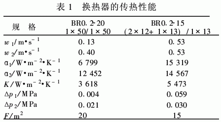
This example shows that choosing a different process under the same load can save equipment investment by 25%. However, the multi-process design will result in: 1The inlet and outlet of the hot and cold medium can only be installed on both sides of the fixed plate and the movable plate, which brings inconvenience to the installation and maintenance of the heat exchanger. 2 Because the heat medium adopts multiple processes, the fluid resistance increases, and the operating cost of the equipment increases. 3 The hot and cold medium is not all countercurrent between the plates, which affects the heat transfer effect. 4 The use of multiple processes can easily cause blockage between the plates, which is not conducive to the operation of the whole machine.
2·2 The use of unequal-section plate heat exchangers for the disadvantages of multi-process design, plate heat exchangers with different heat and cold flow cross sections can be used. By adjusting the flow cross-sectional area on both sides of the heat exchanger, the flow velocity between the plates on both sides can be adjusted, and the convective heat transfer coefficient α value on the side with a small amount of medium treatment can be improved, thereby achieving the purpose of improving the heat transfer effect of the whole machine. At present, this is a solution that is ideal when the heat transfer effect of a common plate heat exchanger is not good in the unequal temperature heat transfer.
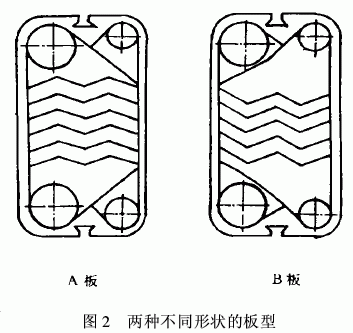
The structure of this heat exchanger is shown in Figure 1. It is composed of two different shapes of A and B plates, as shown in Figure 2. A large flow cross section F1 is formed on the front surface of the A plate and the reverse side of the B plate, and the reverse side of the A plate forms a small flow cross section F2 with the front surface of the B plate, and F1:F2=C. Adjusting the C value can make the plate heat exchanger obtain reasonable heat and heat convection heat transfer coefficient α1, α2 value, so that the plate heat exchanger K value reaches a reasonable value. 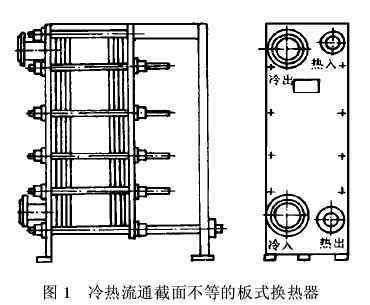
Next, a practical heating condition will be discussed, that is, the adaptability of the unequal section plate heat exchanger to the heating condition will be analyzed. The working condition parameters are: one hot water temperature 130~80°C, and the secondary hot water temperature 95~70°C. The ratio of the volume flow rate V1 of the primary hot water to the volume flow rate V2 of the secondary hot water is 1:2. For this condition, the ratio of the flow cross-sectional area of ​​the plate heat exchanger should be defined as: F'1:F'2 =1:2. In this way, the flow velocity w1′=w2′ between the cold and hot plates of the heat exchanger under this condition can be ensured, and the convective heat transfer coefficients α1 and α2 and the resistance drops Δp1′ and Δp2′ can be kept within a reasonable range. A comparison is made between a common plate heat exchanger of the above working conditions and a unequal section plate heat exchanger. Assume that the sum of the cross-sectional area of ​​the single-channel cold-heat flow of the ordinary plate heat exchanger (F1+F2) is equal to the sum of the cross-sectional area of ​​the single-channel cold-heat flow of the unequal-section plate heat exchanger (F'1+F'2), that is, (F1+F2)=F'1+F'2=2F, so F1=F2=F, and F'1=(2/3)F, F'2=(4/3)F. It is known from heat transfer and fluid mechanics that when the fluid flows in the heat exchanger, the convective heat transfer coefficient α and the flow path resistance between the fluid and the heat transfer surface can be expressed by the following criterion equation: 
Nu---Nucher number, Nu=αde/λ
Re---Reynolds number, Re=wde/λ
Pr---Prandtl number Eu---Eulerian number, Eu=Δp/(Ïw2)
De---heat exchanger single channel equivalent straight, m
Δp---fluid resistance drop, MPa
w---fluid flow rate between heat exchanger plates, m/s
Ï---fluid density, kg/m3
λ---fluid thermal conductivity, W/(m·K)
Ï…---The kinematic viscosity of the fluid, m2/s
----the convective heat transfer coefficient between the fluid and the wall in the flow channel, W / (m2 · K) C, C1, n, n1 is a constant.
From equations (1) and (2): 
We know that when the fluid flows through the channel formed by a certain type of plate, if the fluid volume flow V and the inlet and outlet temperature T do not change, Re and Pr also do not change. If the ordinary plate heat exchanger is used in this working condition, the α and Δp on the primary side are: 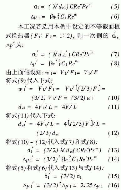
It can be seen from equations (15) and (16) that under the same working condition, the common side and the unequal section plate heat exchangers with the same cross-sectional area on both sides of the hot and cold are the primary side. The convective heat transfer coefficient α1' is increased by 50% compared with the former convective heat transfer coefficient α1, thereby greatly improving the heat transfer performance of the plate heat exchanger. Although the primary side resistance is 2·25 times higher than that of the conventional plate heat exchanger (Equation (16)), since the resistance of the original ordinary plate heat exchanger is extremely low, the increase in the current resistance will not exceed the allowable resistance value of the system. And the resistance increase is not large compared with the heat exchanger that changes the heat transfer effect by designing multiple processes.
At this point, the author believes that since most of the heating conditions are unequal temperature difference heat transfer, that is, the processing capacity on both sides of the hot and cold is not equal, so the unequal cross-section plate heat exchanger is a kind of heating. The ideal heat exchange equipment is the ideal solution for the poor heat transfer effect in most heating conditions. Manufacturers are encouraged to actively develop such products.
2. 3 Import and export plus bypass pipe in the form of a bypass pipe between the heat exchanger inlet and outlet, see Figure 3. By controlling the opening of the regulating valve and the amount of water entering the heat exchanger, the requirements of the system for the resistance of the heat exchanger can be met, and the water flowing through the bypass pipe is mixed with the water at the outlet of the heat exchanger to reach the water supply temperature required by the system. This device is a kind of mitigation measure for the common plate heat exchanger that has to increase the heat transfer area of ​​the heat exchanger due to the excessive side resistance of the large processing volume under the unequal temperature difference heat transfer condition. It can only be used in the large-end differential heat transfer conditions of ordinary heat exchangers, and at the cost of consuming heat transfer driving force inside the heat exchanger. This can be seen from the actual heating conditions below. 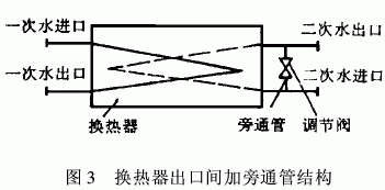
For example, in a heating condition, the temperature of the primary hot water is 130~80 °C, and the temperature of the secondary hot water is 95~70 °C. A logarithmic mean temperature difference Δtm1 of a unequal-section plate heat exchanger having a reasonable plate type is used at 20 °C.
If a bypass device is added to the ordinary plate heat exchanger, the temperature of the primary side of the fluid flowing through the heat exchanger can be determined to be 130-80 ° C, and the temperature of the secondary side is 120-70 ° C, and the logarithmic average The temperature difference is:
Δtm1=[(T1-t2)+(T2-t1)]/2=
[(130-120)+(80-70)]/2=10(17)
It can be seen from the equations (17) and (18) that the logarithmic mean temperature difference between the plate heat exchanger with the bypass tube and the unequal section plate heat exchanger is reduced by 50%. The heat transfer quantity Q is equal in two heat exchangers (ie, unequal section plate heat exchangers and ordinary plate heat exchangers with bypass pipes), ie Q=Q1=Q2, heat transfer coefficient K value They should also be approximately equal. For a unequal-section plate heat exchanger with a reasonable plate shape, the resistance value should be within a reasonable range. According to the formula of heat transfer coefficient K: 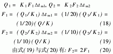
It can be seen that the common plate heat exchanger with the bypass pipe device is selected for the working condition, and the heat exchange area of ​​the plate heat exchanger with the unequal flow cross section with a reasonable plate type is increased by 100%, that is, the bypass pipe is selected. The plate heat exchanger is twice as expensive as the investment in a unequal-section plate heat exchanger with a reasonable plate shape. The author believes that in the heating system, this kind of bypass device can only be used as a mitigation measure in the system for the versatility of the plate heat exchanger with a large difference in the amount of heat and heat medium treatment. It cannot replace the unequal measures. The role of the section plate heat exchanger in the heating system. With the increase in the variety of heat exchangers and their adaptability to working conditions, such devices will lose their role in the use of plate heat exchangers.
3 Conclusion System operating conditions have a great influence on the plate heat exchanger. The main reason is the adaptation of the plate heat exchanger structure to the system working conditions. That is, different system working conditions require plate heat exchangers with different structures, otherwise it will not be reached. Zui good heat transfer effect. Among the three solutions listed above, the author believes that the second type (using unequal flow section plate heat exchangers in most heat transfer conditions) is currently the ideal solution and should be promoted. In short, in the future development, design and production of plate heat exchangers, the structure of the plate heat exchanger should be adapted to the requirements of the system as much as possible to reduce or eliminate the heat transfer performance of the plate heat exchanger. The effect is to achieve good heat transfer, achieve energy saving, save investment and improve economic efficiency.
Discussion on the influence of system working conditions on heat transfer performance of plate heat exchanger
China has been developing plate heat exchangers since the 1960s. In the mid-1980s, plate heat exchangers were used in heating systems. With the continuous expansion of China's central heating systems, the demand for plate heat exchangers is increasing. The form of plate heat exchangers currently produced in China is still relatively simple, and there are still many problems in the heat exchangers operating in the real heating system. The author believes that the main problem at present is that the effects of plate heat exchangers are not fully utilized in most heating conditions. Let's discuss this issue and analyze and compare some of the current solutions to this problem.
